The Raspberry Pi 40-pin GPIO header is one of the features that makes the Raspberry Pi useful for electronics projects, home automation, robotics, sensors, displays, and hardware interfaces.
This Raspberry Pi pinout guide explains what each physical pin does, how GPIO numbering works, and how to use the most common interfaces, including I2C, SPI, and UART.
It also explains the difference between physical pin numbers and GPIO/BCM numbers, which is one of the most common sources of confusion when starting with Raspberry Pi projects.
Important: Raspberry Pi GPIO pins use 3.3V logic. Connecting a 5V signal directly to a GPIO input can damage the Raspberry Pi.
Raspberry Pi 40-Pin GPIO Header
Most modern Raspberry Pi boards use the standard 40-pin GPIO header.
The 40-pin header provides:
- General-purpose input/output pins
- 3.3V power
- 5V power
- Ground connections
- I2C
- SPI
- UART
- PWM and other alternate functions
- Interfaces for HATs and other expansion boards
The 40-pin header uses a 2.54 mm (0.1-inch) pitch.
The physical pins are numbered from 1 to 40.
However, the GPIO numbers used by software are different from the physical pin numbers.
This distinction is important when following Raspberry Pi tutorials.
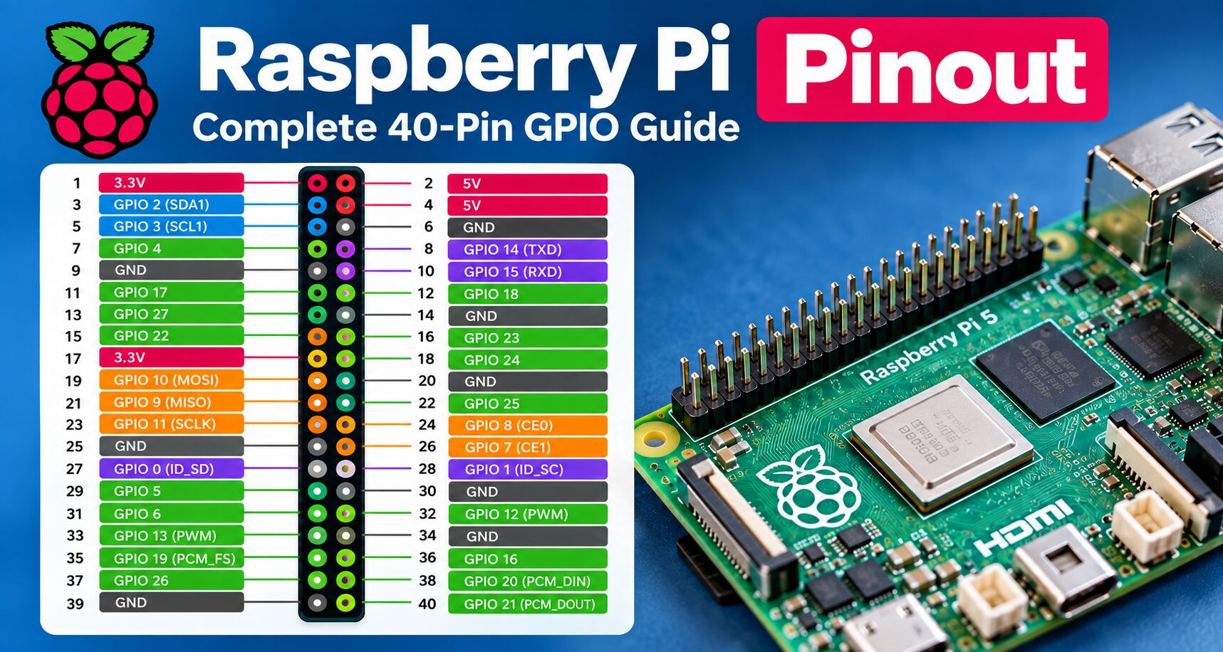
Raspberry Pi Pinout Diagram
The standard Raspberry Pi 40-pin header can be represented as follows:
| Physical Pin | Function | GPIO / BCM | Function | Physical Pin |
|---|---|---|---|---|
| 1 | 3.3V | — | 5V | 2 |
| 3 | GPIO 2 | SDA1 / I2C | 5V | 4 |
| 5 | GPIO 3 | SCL1 / I2C | GND | 6 |
| 7 | GPIO 4 | GPIO | GPIO 14 | 8 |
| 9 | GND | — | GPIO 15 | 10 |
| 11 | GPIO 17 | GPIO | GPIO 18 | 12 |
| 13 | GPIO 27 | GPIO | GND | 14 |
| 15 | GPIO 22 | GPIO | GPIO 23 | 16 |
| 17 | 3.3V | — | GPIO 24 | 18 |
| 19 | GPIO 10 | SPI0 MOSI | GND | 20 |
| 21 | GPIO 9 | SPI0 MISO | GPIO 25 | 22 |
| 23 | GPIO 11 | SPI0 SCLK | GPIO 8 | 24 |
| 25 | GND | — | GPIO 7 | 26 |
| 27 | GPIO 0 | ID_SD | GPIO 1 | 28 |
| 29 | GPIO 5 | GPIO | GND | 30 |
| 31 | GPIO 6 | GPIO | GPIO 12 | 32 |
| 33 | GPIO 13 | PWM | GND | 34 |
| 35 | GPIO 19 | SPI/PCM | GPIO 16 | 36 |
| 37 | GPIO 26 | GPIO | GPIO 20 | 38 |
| 39 | GND | — | GPIO 21 | 40 |
Raspberry Pi’s official documentation identifies the standard GPIO mappings for interfaces such as I2C, SPI and serial communication.
Physical Pin Number vs GPIO Number
There are two numbering systems you will encounter in Raspberry Pi tutorials.
Physical pin number
This is the number printed or referenced according to the position on the 40-pin header.
For example:
Physical pin 11
is located at position 11 on the header.
GPIO / BCM number
The same physical pin is:
GPIO 17
So:
Physical pin: 11
GPIO/BCM:     17
This distinction is extremely important when writing Python programs.
For example, if a tutorial says:
GPIO 17you should not automatically connect your component to physical pin 17.
GPIO 17 is located on physical pin 11.
Raspberry Pi GPIO Pinout Table
The following table provides a more practical reference for the commonly used pins.
| Physical Pin | BCM GPIO | Primary Function |
|---|---|---|
| 1 | — | 3.3V |
| 2 | — | 5V |
| 3 | GPIO 2 | I2C SDA |
| 4 | — | 5V |
| 5 | GPIO 3 | I2C SCL |
| 6 | — | GND |
| 7 | GPIO 4 | GPIO |
| 8 | GPIO 14 | UART TX |
| 9 | — | GND |
| 10 | GPIO 15 | UART RX |
| 11 | GPIO 17 | GPIO |
| 12 | GPIO 18 | GPIO / PWM |
| 13 | GPIO 27 | GPIO |
| 14 | — | GND |
| 15 | GPIO 22 | GPIO |
| 16 | GPIO 23 | GPIO |
| 17 | — | 3.3V |
| 18 | GPIO 24 | GPIO |
| 19 | GPIO 10 | SPI MOSI |
| 20 | — | GND |
| 21 | GPIO 9 | SPI MISO |
| 22 | GPIO 25 | GPIO |
| 23 | GPIO 11 | SPI SCLK |
| 24 | GPIO 8 | SPI CE0 |
| 25 | — | GND |
| 26 | GPIO 7 | SPI CE1 |
| 27 | GPIO 0 | ID_SD |
| 28 | GPIO 1 | ID_SC |
| 29 | GPIO 5 | GPIO |
| 30 | — | GND |
| 31 | GPIO 6 | GPIO |
| 32 | GPIO 12 | GPIO / PWM |
| 33 | GPIO 13 | GPIO / PWM |
| 34 | — | GND |
| 35 | GPIO 19 | GPIO / SPI / PCM |
| 36 | GPIO 16 | GPIO |
| 37 | GPIO 26 | GPIO |
| 38 | GPIO 20 | GPIO / SPI / PCM |
| 39 | — | GND |
| 40 | GPIO 21 | GPIO / SPI / PCM |
The exact alternate functions available depend on the Raspberry Pi model and configuration. Raspberry Pi’s documentation should be used when a project requires a specific peripheral mapping.
Raspberry Pi Power Pins
The GPIO header contains dedicated power pins.
3.3V
There are two 3.3V pins:
- Physical pin 1
- Physical pin 17
These provide the Raspberry Pi’s 3.3V supply.
5V
There are two 5V pins:
- Physical pin 2
- Physical pin 4
These are connected to the Raspberry Pi’s 5V power rail.
Ground
Several pins are connected to ground:
- 6
- 9
- 14
- 20
- 25
- 30
- 34
- 39
Ground connections are commonly used to complete circuits between the Raspberry Pi and external components.
Raspberry Pi GPIO Pins
GPIO stands for General Purpose Input/Output.
A GPIO can generally be configured as either an input or an output.
GPIO as an input
An input allows the Raspberry Pi to read a signal.
For example:
- Push buttons
- Motion sensors
- Door sensors
- Switches
- Digital sensors
The Raspberry Pi can read a GPIO as either a logical high or low state.
GPIO as an output
An output allows the Raspberry Pi to control another device.
Examples include:
- LEDs
- Relays
- Buzzers
- Transistors
- Control signals
- Automation equipment
The GPIO output uses 3.3V logic.
Raspberry Pi GPIO Voltage
One of the most important rules when working with the Raspberry Pi GPIO header is:
GPIO pins are not 5V tolerant.
The GPIO logic level is based on 3.3V.
Do not connect a 5V output directly to a Raspberry Pi GPIO input.
For example, connecting a 5V sensor output directly to a GPIO pin can damage the Raspberry Pi.
If you need to connect a 5V device, use an appropriate:
- Logic-level converter
- Voltage divider
- Interface circuit
- Level-shifting module
Raspberry Pi explicitly warns users not to connect 5V signals to 3.3V GPIO components.
Raspberry Pi I2C Pins
I2C is a two-wire communication protocol commonly used with sensors and displays.
The standard Raspberry Pi I2C pins are:
| Function | GPIO | Physical Pin |
|---|---|---|
| SDA | GPIO 2 | 3 |
| SCL | GPIO 3 | 5 |
Typical I2C devices include:
- Temperature sensors
- OLED displays
- LCD controllers
- RTC modules
- Environmental sensors
- ADC/DAC modules
Multiple I2C devices can share the same SDA and SCL lines when they use different addresses.
Raspberry Pi SPI Pins
SPI is commonly used for higher-speed communication with peripherals.
The standard SPI0 interface uses:
| SPI Function | GPIO | Physical Pin |
|---|---|---|
| MOSI | GPIO 10 | 19 |
| MISO | GPIO 9 | 21 |
| SCLK | GPIO 11 | 23 |
| CE0 | GPIO 8 | 24 |
| CE1 | GPIO 7 | 26 |
Raspberry Pi documentation lists these pins as the standard SPI0 mapping.
SPI is commonly used with:
- Displays
- ADCs
- DACs
- Sensors
- RFID readers
- Flash memory
- Other high-speed peripherals
Raspberry Pi UART Pins
The standard serial interface uses:
| UART Function | GPIO | Physical Pin |
|---|---|---|
| TX | GPIO 14 | 8 |
| RX | GPIO 15 | 10 |
UART is useful for communicating with:
- Microcontrollers
- GPS modules
- Serial devices
- Embedded systems
- Debug consoles
Remember that UART connections are normally crossed:
Raspberry Pi TX → Device RX
Raspberry Pi RX → Device TX
Raspberry Pi GND → Device GND
What Are GPIO Alternate Functions?
A GPIO pin does not necessarily have only one purpose.
Depending on the Raspberry Pi model and configuration, a GPIO can provide different alternate functions.
For example, a pin can potentially be used for:
- GPIO
- SPI
- I2C
- UART
- PWM
- PCM
- Other peripheral functions
This is why a pinout diagram can contain several labels for the same physical pin.
The Raspberry Pi documentation provides detailed mappings for the available interfaces.
Raspberry Pi 5 GPIO Pinout
The Raspberry Pi 5 continues to use the standard 40-pin Raspberry Pi GPIO header.
This means that many existing Raspberry Pi HATs and GPIO accessories remain compatible with the Raspberry Pi 5.
However, Raspberry Pi 5 uses the RP1 I/O controller for much of its peripheral functionality. For example, SPI functionality on Raspberry Pi 5 is provided by RP1 rather than directly by the main application processor.
For most projects, you can continue using the familiar physical pin numbering and standard GPIO mappings.
For advanced hardware development, however, consult the Raspberry Pi 5 documentation and RP1 peripheral documentation rather than relying exclusively on an older pinout diagram.
Is the Raspberry Pi 5 Pinout the Same as Raspberry Pi 4?
For the standard 40-pin header, the Raspberry Pi 5 maintains the same familiar physical GPIO header layout.
This is one reason the Raspberry Pi ecosystem can reuse many existing GPIO accessories.
However, the underlying hardware has changed.
Raspberry Pi 5 uses the RP1 I/O controller and provides additional interfaces elsewhere on the board, including a PCIe interface and dedicated connectors for other peripherals.
So there is an important distinction:
The 40-pin header remains familiar, but the underlying I/O architecture is not identical to earlier Raspberry Pi generations.
Raspberry Pi GPIO Projects
Once you understand the pinout, you can use the GPIO header for a wide range of projects.
Some common Raspberry Pi projects include:
LEDs
Use a GPIO output to turn an LED on or off.
Always use an appropriate resistor with an LED.
Buttons
Configure a GPIO as an input to detect when a button is pressed.
Sensors
Connect digital sensors using GPIO, I2C, or SPI.
Displays
Small OLED and LCD displays frequently use I2C or SPI.
Home Automation
GPIO can be used to interface with:
- Relays
- Motion sensors
- Door sensors
- Temperature sensors
- Lighting controllers
Raspberry Pi Home Server
The GPIO header can also be useful for monitoring and controlling hardware in home-server projects.
For example, you could connect:
- Temperature sensors
- Cooling fans
- Status LEDs
- UPS monitoring hardware
How to Check the Raspberry Pi Pinout From the Terminal
Raspberry Pi OS includes the pinout command through the GPIO Zero software.
Open a terminal and run:
pinoutThis displays a GPIO reference for the Raspberry Pi you’re using. Raspberry Pi specifically documents this command as a way to access a GPIO pinout reference directly from the system.
This is particularly useful when working remotely over SSH because you don’t need to keep a physical pinout diagram nearby.
Raspberry Pi GPIO Safety
Before connecting anything to the GPIO header, keep these rules in mind:
1. Never connect 5V directly to a GPIO input
Raspberry Pi GPIO uses 3.3V logic.
2. Use resistors with LEDs
An LED should not normally be connected directly to a GPIO without current limiting.
3. Don’t drive motors directly from GPIO
Motors can require substantially more current and can generate electrical noise and voltage spikes.
Use a:
- Motor driver
- H-bridge
- Transistor circuit
- Appropriate external power supply
Raspberry Pi’s documentation specifically recommends using an H-bridge or motor controller rather than connecting motors directly to GPIO pins.
4. Connect grounds correctly
The Raspberry Pi and external circuit generally need a common ground when communicating through GPIO.
5. Check the peripheral voltage
Before connecting a sensor or module, verify whether its logic level is:
- 3.3V
- 5V
- Another voltage
6. Double-check the pin number
Always determine whether the instructions you’re following use:
- Physical numbering
- BCM numbering
- WiringPi numbering
Mixing numbering systems is a common cause of wiring errors.
Physical GPIO Numbering vs BCM Numbering
Here’s a simple example.
Suppose your Python program says:
GPIO 17GPIO 17 is not physical pin 17.
It corresponds to:
BCM GPIO 17
Physical pin 11
Likewise:
GPIO 2 → physical pin 3
GPIO 3 → physical pin 5
GPIO 14 → physical pin 8
GPIO 15 → physical pin 10
Always check the numbering convention used by your software library.
Raspberry Pi Pinout Resources
For a visual and interactive Raspberry Pi pin reference, you can also use Pinout.xyz, which provides an interactive GPIO reference and information about Raspberry Pi expansion boards and HATs.
The official Raspberry Pi documentation is the better reference when you need authoritative information about a particular Raspberry Pi model or alternate peripheral function.
Raspberry Pi GPIO FAQ
How many GPIO pins does a Raspberry Pi have?
The Raspberry Pi uses a 40-pin header, but not all 40 pins are GPIO.
The header also contains 3.3V, 5V and ground connections, as well as pins with special functions.
Are Raspberry Pi GPIO pins 5V tolerant?
No. Raspberry Pi GPIO uses 3.3V logic. A 5V signal should not be connected directly to a GPIO input.
What is the Raspberry Pi GPIO pinout?
The Raspberry Pi GPIO pinout describes the functions and numbering of the pins on its 40-pin expansion header.
What is GPIO 17 on Raspberry Pi?
GPIO 17 is BCM GPIO 17 and corresponds to physical pin 11.
Which Raspberry Pi pins are 5V?
Physical pins 2 and 4 provide 5V.
Which Raspberry Pi pins are 3.3V?
Physical pins 1 and 17 provide 3.3V.
Which Raspberry Pi pins are ground?
The standard ground pins include:
6, 9, 14, 20, 25, 30, 34 and 39.
Which Raspberry Pi pins are used for I2C?
The standard I2C interface uses:
- GPIO 2 / physical pin 3 — SDA
- GPIO 3 / physical pin 5 — SCL
Which Raspberry Pi pins are used for SPI?
The standard SPI0 mapping uses:
- GPIO 10 / pin 19 — MOSI
- GPIO 9 / pin 21 — MISO
- GPIO 11 / pin 23 — SCLK
- GPIO 8 / pin 24 — CE0
- GPIO 7 / pin 26 — CE1
Which Raspberry Pi pins are UART?
The standard UART pins are:
- GPIO 14 / physical pin 8 — TX
- GPIO 15 / physical pin 10 — RX
Final Thoughts
The Raspberry Pi 40-pin GPIO header is one of the most useful features of the platform. It allows the Raspberry Pi to communicate with sensors, displays, HATs, motors, LEDs, automation hardware and many other peripherals.
The most important thing to remember is that physical pin numbers and GPIO/BCM numbers are different.
For everyday projects, keep a pinout reference nearby and verify the voltage requirements of every component before connecting it.
For Raspberry Pi 5 and other newer boards, use the official Raspberry Pi documentation when you need detailed information about alternate functions or peripheral mappings.